Introduction
This part of the DIY vocoder building guide describes all necessary steps, PCB’s and components to complete the vocoder in its basic configuration.
Click here to go to the BOM section.
PCB stuffing
In this chapter the following parts will be addressed:
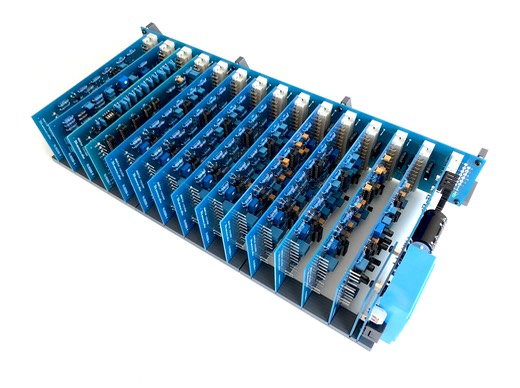
Backplane - PCB reference RU80068.1
Power supply - PCB reference RU80068.2
Input/output module - PCB reference RU80068.3
Band pass filter - PCB reference RU80068.4
Low pass filter - PCB reference RU80068.5
High pass filter - PCB reference RU80068.6
Click the above links for detailed instructions.
Soldering instructions
This quick guide focuses on soldering for the beginner and explains how you can solder a variety of components using a few different techniques. Although soldering can seem daunting at first, once you give it a try you will see that in most applications it's quite simple to do.
If you do not have a mediocre soldering experience, do not build this kit as first project. Practice your soldering skills on smaller projects. This project is not difficult in itself but it is extensive in the number of components.
Start with the smallest components working up to the taller components.
Place the component into the board on the indicated position, making sure it goes in the right way around and the part sits flush against the board. Bend the legs only slightly to secure the part. Place the board so you can easily access the pads with a soldering iron.
Use a soldering iron with limited power and make sure the soldering iron has warmed up. If necessary use a brass soldering iron cleaner or damp sponge to clean the tip.
Pick up the soldering Iron in one hand and the solder wire in the other hand, place the soldering iron tip on the pad, feed a small amount of solder into the joint. The solder should melt on the pad and flow around the component leg.
Remove the solder, then remove the soldering iron. Maintain a maximum heating time of 10 seconds. Leave the joint to cool for a few seconds, then using a pair of cutters trim the excess component lead.
Warranty
This is a DIY soldering kit that you build yourself. The warranty periode is equal to the minimum legal warranty requirement in the country of the buyer or limited to 6 months in absence of such legal requirement. No warranty is given on defective PCB's due to inadequate soldering techniques and/or component misplacements.
The seller can not be held liable for direct or indirect damages for any amount higher than the purchase price of the product.