Introduction
Estimated building time: 0,1 hours.
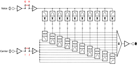
The core of the vocoder is his basic configuration mainly uses 10 analog band pass filters causing the impossibility to reproduce unvoiced sounds as f, s, t, k and p. The inclusion of the high frequency blend adjustable by P117 (the second potentiometer on the high pass band filter) does not completely solve this shortcoming.
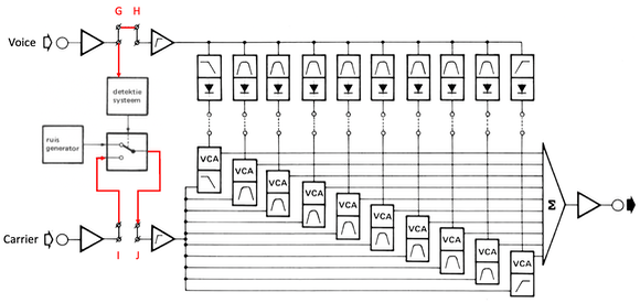
However the sibilance expansion fully eliminates this imperfection by adding a voiced/unvoiced detector/switch and a noise generator.
Basic configuration
Block diagram of the vocoder in his basic configuration:
Sibilance expansion
Block diagram of the vocoder with sibilance expansion:
Jumper settings
To use the vocoder in the basic configuration but also to adjust the input/output module as well all filter boards, connect pin G + pin H and on top of that also pin I + pin J. These connections can be made either by wire on the foreseen pins at the right side of the backplane, either by bridging both solder jumpers at the backside of the backplane.
To fully enjoy the capabilities of the vocoder, it is recommended to switch on the sibilance expansion by only connecting pin G + pin H, or by bridging the proper solder jumper at the backside of the backplane.
Well done
You have finished this section, so click here to navigate back to the assembly & adjustment instructions.