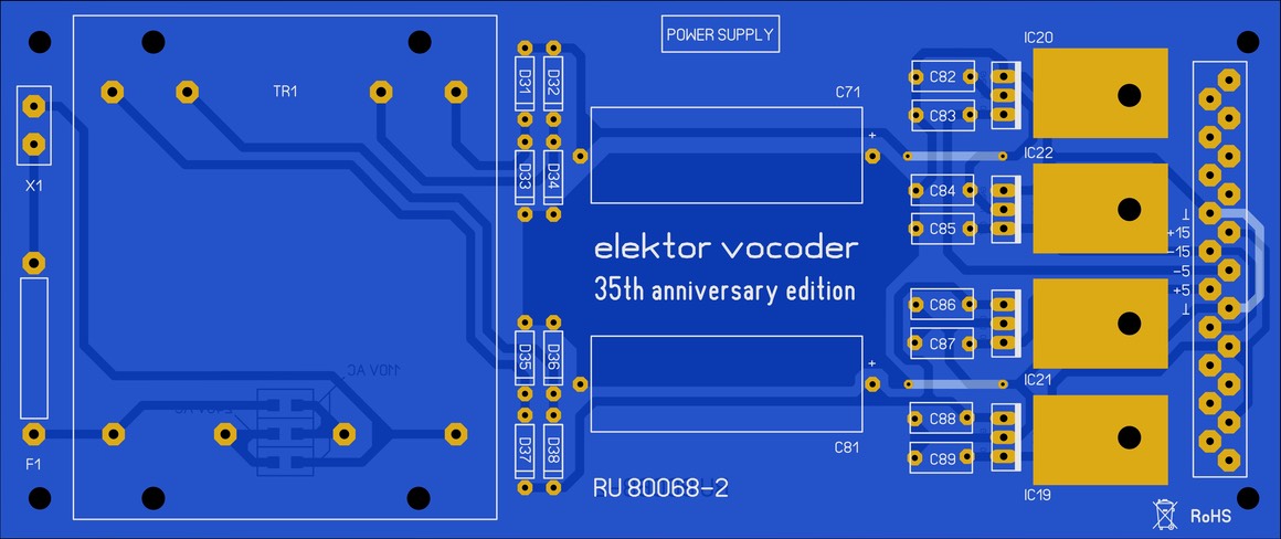
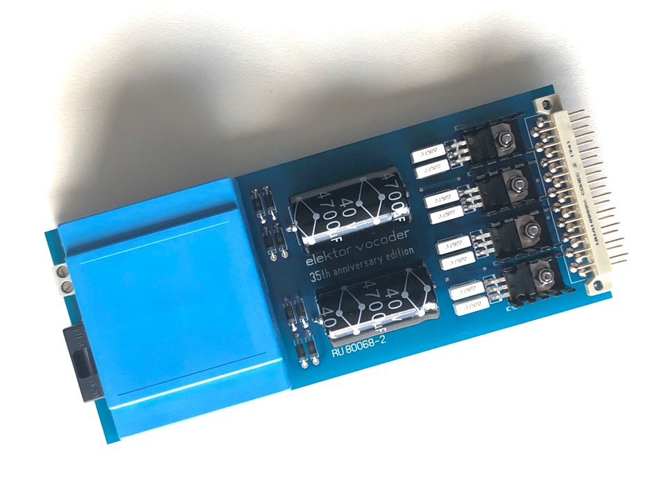
PCB reference RU80068.2
Estimated building time: 2 hours
To complete this step the PCB with reference RU80068.2 is required.
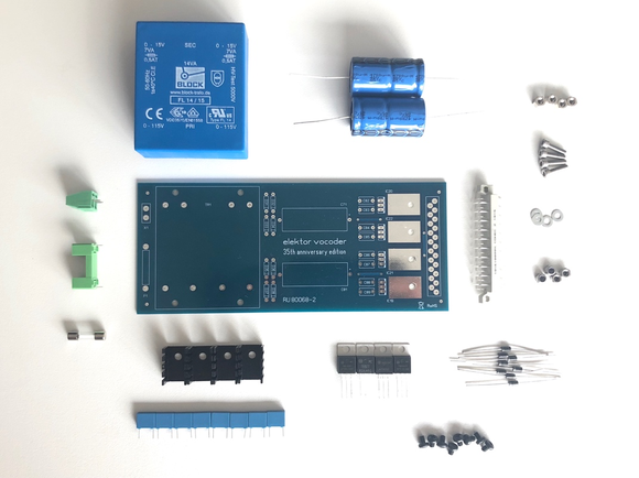
Sort all required components as indicated in the BOM:
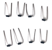
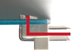
Bend
the diodes so that they fit neatly right away:
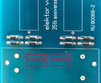
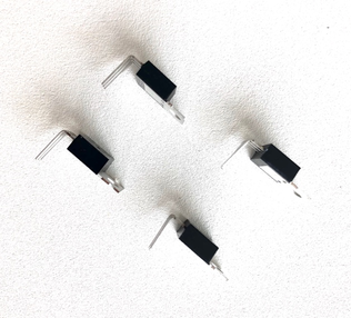
Solder
the 8 diodes, note the direction of the white line (component) and tabbed
indication (silkscreen). Do not reverse the polarity of these components:
Put
the 21 pin connector to the board, do not exert
any excessive force. Solder
only pin 1 and pin 21 and check for a right angle. Correct if necessary and
solder all remaining pins:
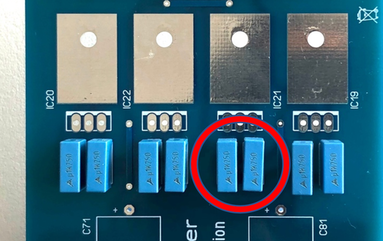
Place
the 100 nF film capacitors and start soldering only 1 of both legs. This allows
lining up the components. Correct if necessary and solder all remaining legs:
Bend
the power regulators so that
they fit neatly right away:
Fasten
the PCB, heat sinks and regulators together with nuts & bolts and do not
forget to apply some washers. Thermal paste is not necessary due to the limited
dissipation in the regulators. Allign the heat sinks before tightening the nuts & bolts.
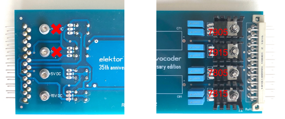
Check twice the right regulator is on the right place:
IC19 = 7815
IC20 = 7905
IC21 = 7805
IC22 = 7915
On the prototyping boards the -15V DC & -5V DC indication on the solder side is exchanged,
so do not use this indication as reference. Only rely on the above
regulator list and the below pictures to put the components in place:
Apply some Loctite on the bolts to fix the power supply
cover plate. The hex bushing is no longer accessible after soldering the
transformer, so do not skip this step. Superglue can do the job as well, but
loosening in any case becomes very difficult:
Fasten
the 4 screws and bushings:
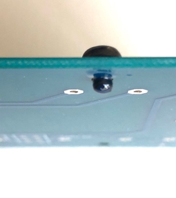
Solder
the tranformer on the PCB, be carefull while bending the pins as they will
break down if you are too rough. Apply pretty much solder wire and let it flow
through the plated hole as this wil fix the transformer also on the component
side of the PCB:
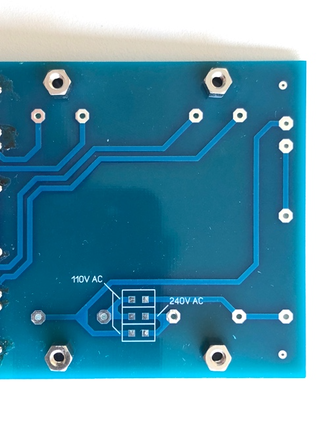
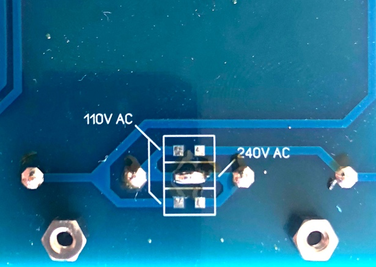
Select the mains voltage of your country
by bridging the jumpers on the right position. For 110V AC both 2 bridges should
be applied, for 240V AC only one brigde should be closed. Check
twice before you proceed:
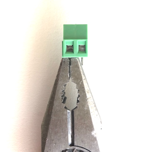
Insert
the AC terminal block and make a solid solder connection. Depending on the
choosen model it may happen that the connector legs are square, in that case
use a plier to squeeze the pins a little. Do
not exert any excessive force while inserting the AC terminal block to avoid damaging the plated holes:
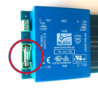
Put
the fuseholder and fuse in place. Do not forget to cover the fuseholder,
otherwise mains voltage can be touched:
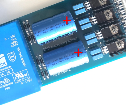
Bend
the electrolytic
capacitors (e-caps) and put them in the right position. Do not reverse the polarity of these
components:
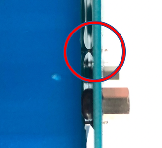
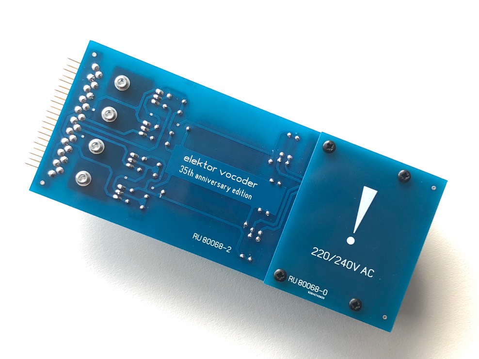
Thoroughly clean the PCB using flux cleaner and check for bad soldering or tin bulbs. Try not to touch the transformer as the white imprint will disappear as can seen on the below picture:
Place the power supply cover over the AC current parts and screw the lid in place.
Well done
Congratulations, you have finished the power supply section, click here to navigate back to the building guide.