Introduction
Estimated executing time: 4,0 hours.
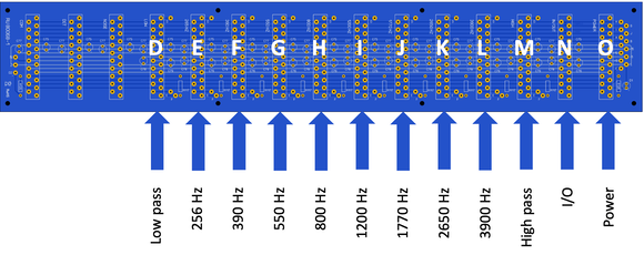
Each filter print has 3 trimpots that must be correctly adjusted. This means that 3 adjustment steps should be performed for each filter board as futher described. Regardless of the filter frequency, the adjustment procedure is exactly the same, only an adapted sine wave in the correct frequency band should be applied.
Carefully follow these steps and troubleshoot any problem before continuing.
Pay attention when adjusting the 2 filters on slot E (256 Hz band pass filter) and slot D (low pass filter). Because of the available space, the sequence here is a little different.
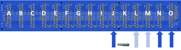
High pass filter
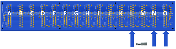
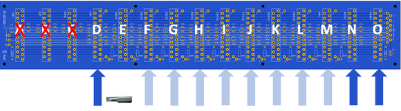
Prepare the backplane in the following configuration. Stricktly follow this order:
O : Power supply
N : Input/output module
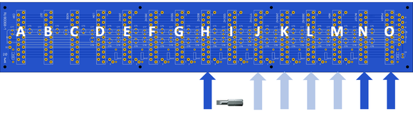
M : Free space for adjustment trimpots
L : High pass filter to adjust (contrary to silkscreen indication on the backplane)
Before connecting all wiring, adjust the DC offset of the high pass filter. Carefully follow the instructions as described below in adjustment step 1.
Afterwards connect the wiring between frontpanel and filter module according to the wiring instructions you can download here.
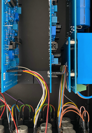
Push the contacts over the pins as far as possible, it should feel like a double click. Bend all cables for the other interfaces a bit to the left so they don’t bother you.
Carefully perform adjustment step 2 and adjustment step 3 as listed below. A suitable 5500 Hz sine wave can be downloaded here.
Then bend all wires in place and snap the high pass filter PCB in the intended slot M as indicated on the silkscreen.
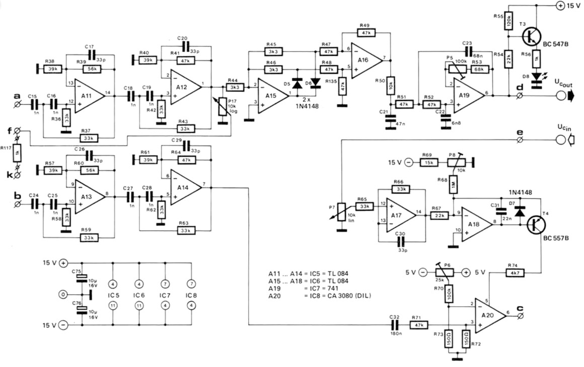
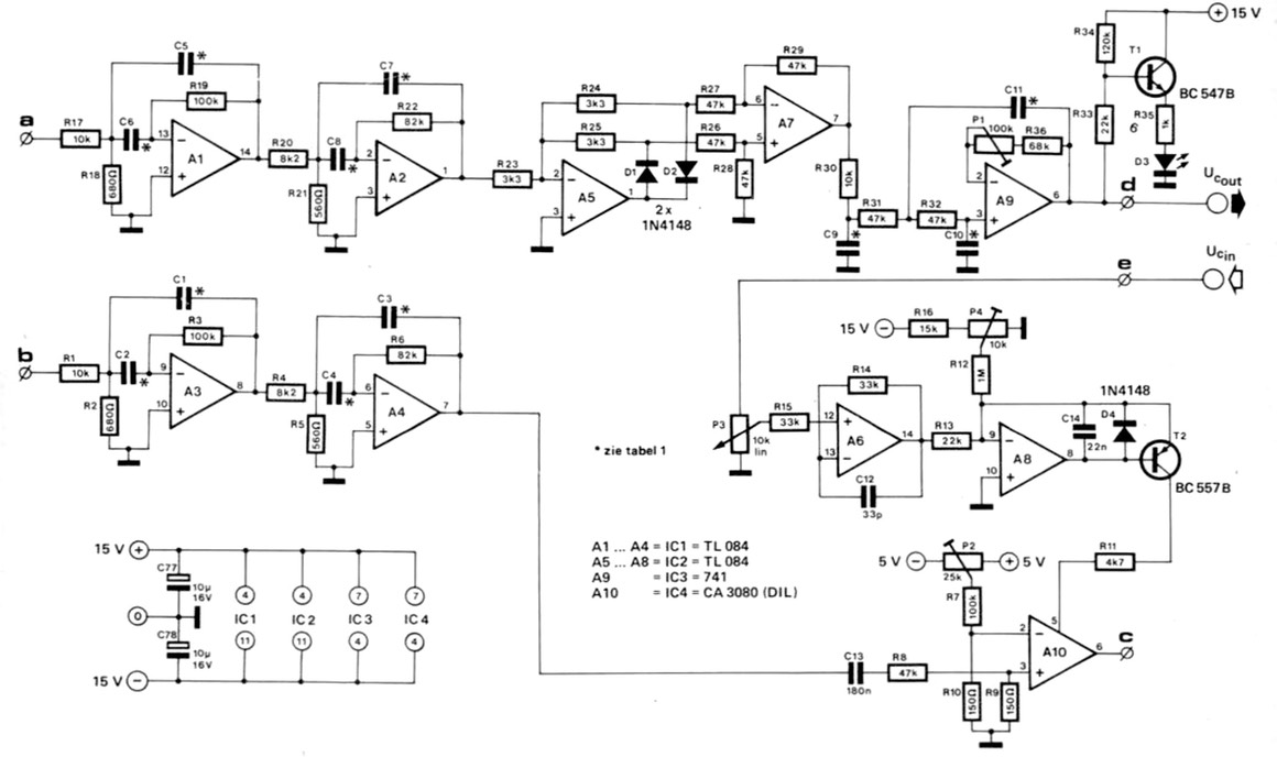
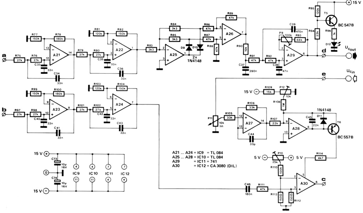
For reference and troubleshooting here is the complete high pass filter circuit as published in the Dutch Elektor magazine from the early 1980’s:
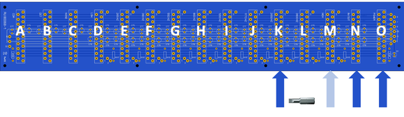
3900 Hz band pass filter
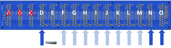
Prepare the backplane in the following configuration. Stricktly follow this order:
O : Power supply
N : Input/output module
M : High pass filter
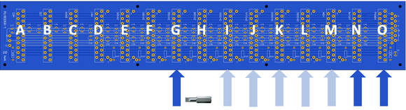
L : Free space for adjustment trimpots
K : 3900 Hz band pass filter to adjust (contrary to silkscreen indication on the backplane)
Before connecting all wiring, adjust the DC offset of the 3900 Hz band pass filter. Carefully follow the instructions as described below in adjustment step 1.
Afterwards connect the wiring between frontpanel and filter module according to the wiring instructions you can download here. Push the contacts over the pins as far as possible, it should feel like a double click. Bend all cables for the other interfaces a bit to the left so they don’t bother you.
Carefully perform adjustment step 2 and adjustment step 3 as listed below. A suitable 3900 Hz sine wave can be downloaded here.
Then bend all wires in place and snap the 3900 Hz band pass filter PCB in the intended slot L as indicated on the silkscreen.
For reference and troubleshooting here is the complete band pass filter circuit as published in the Dutch Elektor magazine from the early 1980’s:
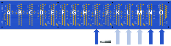
2650 Hz band pass filter
Prepare the backplane in the following configuration. Stricktly follow this order:
O : Power supply
N : Input/output module
M : High pass filter
L : 3900 Hz band pass filter
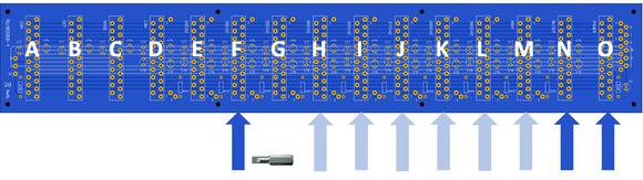
K : Free space for adjustment trimpots
J : 2650 Hz band pass filter to adjust (contrary to silkscreen indication on the backplane)
Before connecting all wiring, adjust the DC offset of the 2650 Hz band pass filter. Carefully follow the instructions as described below in adjustment step 1.
Afterwards connect the wiring between frontpanel and filter module according to the wiring instructions you can download here. Push the contacts over the pins as far as possible, it should feel like a double click. Bend all cables for the other interfaces a bit to the left so they don’t bother you.
Carefully perform adjustment step 2 and adjustment step 3 as listed below. A suitable 2650 Hz sine wave can be downloaded here.
Then bend all wires in place and snap the 2650 Hz band pass filter PCB in the intended slot K as indicated on the silkscreen.
1770 Hz band pass filter
Prepare the backplane in the following configuration. Stricktly follow this order:
O : Power supply
N : Input/output module
M : High pass filter
L : 3900 Hz band pass filter
K : 2650 Hz band pass filter
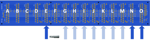
J : Free space for adjustment trimpots
I : 1770 Hz band pass filter to adjust (contrary to silkscreen indication on the backplane)
Before connecting all wiring, adjust the DC offset of the 1770 Hz band pass filter. Carefully follow the instructions as described below in adjustment step 1.
Afterwards connect the wiring between frontpanel and filter module according to the wiring instructions you can download here. Push the contacts over the pins as far as possible, it should feel like a double click. Bend all cables for the other interfaces a bit to the left so they don’t bother you.
Carefully perform adjustment step 2 and adjustment step 3 as listed below. A suitable 1770 Hz sine wave can be downloaded here.
Then bend all wires in place and snap the 1770 Hz band pass filter PCB in the intended slot J as indicated on the silkscreen.
1200 Hz band pass filter
Prepare the backplane in the following configuration. Stricktly follow this order:
O : Power supply
N : Input/output module
M : High pass filter
L : 3900 Hz band pass filter
K : 2650 Hz band pass filter
J : 1770 Hz band pass filter
I : Free space for adjustment trimpots
H : 1200 Hz band pass filter to adjust (contrary to silkscreen indication on the backplane)
Before connecting all wiring, adjust the DC offset of the 1200 Hz band pass filter. Carefully follow the instructions as described below in adjustment step 1.
Afterwards connect the wiring between frontpanel and filter module according to the wiring instructions you can download here. Push the contacts over the pins as far as possible, it should feel like a double click. Bend all cables for the other interfaces a bit to the left so they don’t bother you.
Carefully perform adjustment step 2 and adjustment step 3 as listed below. A suitable 1200 Hz sine wave can be downloaded here.
Then bend all wires in place and snap the 1200 Hz band pass filter PCB in the intended slot I as indicated on the silkscreen.
800 Hz band pass filter
Prepare the backplane in the following configuration. Stricktly follow this order:
O : Power supply
N : Input/output module
M : High pass filter
L : 3900 Hz band pass filter
K : 2650 Hz band pass filter
J : 1770 Hz band pass filter
I : 1200 Hz band pass filter
H : Free space for adjustment trimpots
G : 800 Hz band pass filter to adjust (contrary to silkscreen indication on the backplane)
Before connecting all wiring, adjust the DC offset of the 800 Hz band pass filter. Carefully follow the instructions as described below in adjustment step 1.
Afterwards connect the wiring between frontpanel and filter module according to the wiring instructions you can download here. Push the contacts over the pins as far as possible, it should feel like a double click. Bend all cables for the other interfaces a bit to the left so they don’t bother you.
Carefully perform adjustment step 2 and adjustment step 3 as listed below. A suitable 800 Hz sine wave can be downloaded here.
Then bend all wires in place and snap the 800 Hz band pass filter PCB in the intended slot H as indicated on the silkscreen.
550 Hz band pass filter
Prepare the backplane in the following configuration. Stricktly follow this order:
O : Power supply
N : Input/output module
M : High pass filter
L : 3900 Hz band pass filter
K : 2650 Hz band pass filter
J : 1770 Hz band pass filter
I : 1200 Hz band pass filter
H : 800 Hz band pass filter
G : Free space for adjustment trimpots
F : 550 Hz band pass filter to adjust (contrary to silkscreen indication on the backplane)
Before connecting all wiring, adjust the DC offset of the 550 Hz band pass filter. Carefully follow the instructions as described below in adjustment step 1.
Afterwards connect the wiring between frontpanel and filter module according to the wiring instructions you can download here. Push the contacts over the pins as far as possible, it should feel like a double click. Bend all cables for the other interfaces a bit to the left so they don’t bother you.
Carefully perform adjustment step 2 and adjustment step 3 as listed below. A suitable 550 Hz sine wave can be downloaded here.
Then bend all wires in place and snap the 550 Hz band pass filter PCB in the intended slot G as indicated on the silkscreen.
390 Hz band pass filter
Prepare the backplane in the following configuration. Stricktly follow this order:
O : Power supply
N : Input/output module
M : High pass filter
L : 3900 Hz band pass filter
K : 2650 Hz band pass filter
J : 1770 Hz band pass filter
I : 1200 Hz band pass filter
H : 800 Hz band pass filter
G : 550 Hz band pass filter
F : Free space for adjustment trimpots
E : 390 Hz band pass filter to adjust (contrary to silkscreen indication on the backplane)
Before connecting all wiring, adjust the DC offset of the 300 Hz band pass filter. Carefully follow the instructions as described below in adjustment step 1.
Afterwards connect the wiring between frontpanel and filter module according to the wiring instructions you can download here. Push the contacts over the pins as far as possible, it should feel like a double click. Bend all cables for the other interfaces a bit to the left so they don’t bother you.
Carefully perform adjustment step 2 and adjustment step 3 as listed below. A suitable 390 Hz sine wave can be downloaded here.
Then bend all wires in place and snap the 390 Hz band pass filter PCB in the intended slot F as indicated on the silkscreen.
265 Hz band pass filter
Because of the available space, the sequence here is a little bit different. Do not continue according to the previous method. Slot A, slot B and slot C are lacking supply voltages so filters will not work correctly is these positions.
Prepare the backplane in the following configuration. Stricktly follow this order:
O : Power supply
N : Input/output module
M : High pass filter
L : 3900 Hz band pass filter
K : 2650 Hz band pass filter
J : 1770 Hz band pass filter
I : 1200 Hz band pass filter
H : 800 Hz band pass filter
G : 550 Hz band pass filter
F : 390 Hz band pass filter
E : Free space for adjustment trimpots
D : 265 Hz band pass filter to adjust (contrary to silkscreen indication on the backplane)
Before connecting all wiring, adjust the DC offset of the 265 Hz band pass filter. Carefully follow the instructions as described below in adjustment step 1.
Afterwards connect the wiring between frontpanel and filter module according to the wiring instructions you can download here. Push the contacts over the pins as far as possible, it should feel like a double click. Bend all cables for the other interfaces a bit to the left so they don’t bother you.
Carefully perform adjustment step 2 and adjustment step 3 as listed below. A suitable 265 Hz sine wave can be downloaded here.
Temporary remove the 265 Hz band pass filter and proceed to the low pass filter. Be careful not to short circuit the removed filter and/or other components.
Low pass filter
Because of the available space, the sequence here is a little bit different. Do not continue according to the previous method. Slot A, slot B and slot C are lacking supply voltages so filters will not work correctly is these positions.
Prepare the backplane in the following configuration. Stricktly follow this order:
O : Power supply
N : Input/output module
M : High pass filter
L : 3900 Hz band pass filter
K : 2650 Hz band pass filter
J : 1770 Hz band pass filter
I : 1200 Hz band pass filter
H : 800 Hz band pass filter
G : 550 Hz band pass filter
F : 390 Hz band pass filter
E : Free space for adjustment trimpots
D : Low pass filter to adjust
Before connecting all wiring, adjust the DC offset of the low pass filter. Carefully follow the instructions as described below in adjustment step 1.
Afterwards connect the wiring between frontpanel and filter module according to the wiring instructions you can download here. Push the contacts over the pins as far as possible, it should feel like a double click. Bend all cables for the other interfaces a bit to the left so they don’t bother you.
Carefully perform adjustment step 2 and adjustment step 3 as listed below. A suitable 177 Hz sine wave can be downloaded here.
Finally bend all wires in place and snap the 265 Hz band pass filter PCB in the intended slot E as indicated on the silkscreen.
For reference and troubleshooting here is the complete low pass filter circuit as published in the Dutch Elektor magazine from the early 1980’s:
Handy tip
Use a small screw bit that fits on the choosen trimpots to facilitate the adjustments. Put some heat shrink over the hex holder to prevent short circuits.
Adjustment step 1 - DC offset of all filter boards
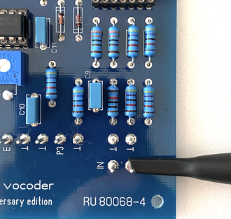
In this step the DC offset of all filter boards will be adjusted. Turn down both both input potentiometers to minimum, do not send any signal into the vocoder.
P1 adjusts the DC offset on the 8 band pass filter boards, P5 adjusts the DC offset on the high pass filter board and P9 adjusts the the DC offset on the low pass filter board.
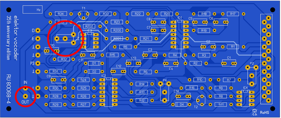
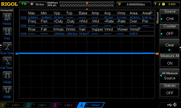
Connect CH4 of an oscilloscope to pin OUT and adjust the DC offset to obtain a minimum output voltage:
Pay attention to select the DC measuring range of your multi meter or oscilloscope, an offset less than 5 mV is the target to aim for.
Adjustment step 2 - Inverting input DC bias voltage of the OTA's
The purpose of this adjustment is to ensure that the varying DC bias voltage derived from the control voltage output of the analyser section when a speech input is present, cannot break through to the vocoded signal output.
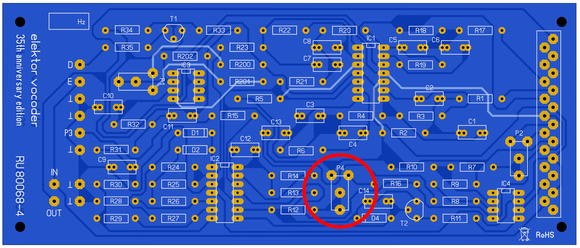
P2 adjusts the DC bias level on the 8 band pass filters, P6 adjusts the DC bias level on the high pass filter and P10 adjusts the DC bias level on the low pass filter.
A steady noise signal should be applied to the speech input. One simple way to do this is to blow gently into the microphone. The bias trimpot on each filter (P2, P6 or P10) is subsequently adjusted for minimum output signal from the vocoder.
If professional measuring equipment is available, a more precise alignment procedure can be considered. Instead of blowing into a microphone, a test signal can be applied direct to the input of the module. A suitable test signal is a 500 Hz or less sinewave, superimposed on a fixed DC voltage.
The output signal from the vocoder can be observed on an oscilloscope, and the preset is adjusted for minimum LF output. Incidentally it may prove impossible to reduce the break-through to an acceptably low level. In this case, the OTA is almost certainly the culprit: in any batch there will always be a few that have too high a leakage from the control input to the output. The only solution is to replace them.
Adjustment step 3 - Preset voltage to current convertor for the OTA’s
This adjustment is intended to set the initial point of the control characteristic to the same level for all modules.
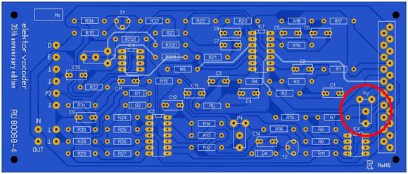
P4 adjusts the voltage to current convertor on the 8 band pass filters, P8 adjusts the the voltage to current convertor on the high pass filter and P12 adjusts the the voltage to current convertor on the low pass filter.
A suitable test signal is applied to the carrier input, white noise is perfect to do this job. A very low DC voltage of approximately 200 mV is applied to the input of the module that is to be adjusted. This calibration voltage can be derived from the +5V DC power supply by means of a 25:1 attenuator.
The trimpot (P4, P8 or P12) can now be adjusted so that an output signal just appears at the main output. If the test voltage proves to be outside the adjustment range of one or more of the modules, the whole procedure can be repeated with a slightly higher or lower test voltage.
Well done
Congratulations, the hardest part is now finished. Provided you respect the jumper settings you can already use the vocoder in its basic configuration.
Click here to navigate to the jumper settings instructons or click here to navigate back to the assembly & adjustment instructions.
In conclusion
With a spectrum analyser and a lot of patience, all filter characterstics are plotted and combined in the below picture. As seen at the left side, the characterstic of the low pass filter is followed by a neat procession of 8 band pass filter characterstics, finally followed by the high pass filter.
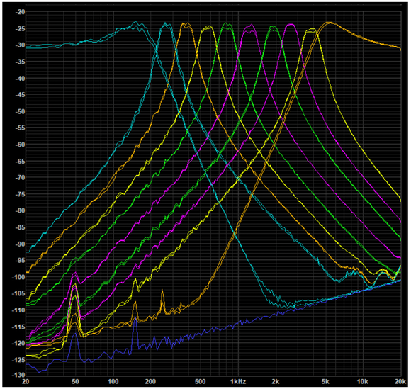
The minor differences in peak amplitude are caused by component tolerances. As can be seen, the filters provide a nicely regular division of the audio spectrum. The high pass filter comes in a little too early, but that has already been solved by slightly changing the corresponding capacitor values.